
(CG), (CD), Thrust Vectors,Horizontal Stabilizers and Static Moments
Part 3
by Greg Gremminger with Mike Jackson as Technical Collaborator
We introduced this series of articles emphasizing that the proficiency requirements of the pilot, to remain in his/her safe flight envelope, may change dramatically with different machines and flight environments. We also discussed that a gyro’s controllability is not necessarily related to its stability or its maneuverability (agility). We emphasized that the stability of the airframe may not necessarily relate to the stability of the whole gyro/pilot system, but that the stability of the airframe may dramatically alter the controllability and pilot proficiency requirements to maintain or restore stability of the whole machine. In order to further appreciate that every machine is a complex interaction of numerous factors, we will begin discussion of the important subjects of STATIC factors of CG, CD, Propeller Thrustline, and Horizontal Stabilizers. These are the factors that initially establish the flight dynamics or ultimate stability of the gyro/pilot system – which, in turn, ultimately effect your personal proficiency requirements to safely fly that machine.
(CG), (CD), Thrust Vectors, Horizontal Stabilizers and Static Moments
Now here’s a fun subject, probably fraught with the most rancor and misunderstanding of any gyro subject. But, these factors are of vital importance to the understanding of your personal safety envelope in your machine because these factors can cause a normally meek and mild machine to be a handful and even dangerous in certain environments—especially at high speeds and/or in turbulence. Let’s start with some Discussion of Terms:
Moment:
A moment is a force acting on a moment arm to rotate the airframe around one of its axis. This is called torque and is the multiplied product of the force (in pounds) times the moment arm (in inches). In this discussion we are primarily interested in pitching moments that will cause the nose of the airframe to pitch upward or downward, around its lateral axis. The stronger the force and/or the longer the moment arm, the faster or more forcefully the airframe will try to pitch up or down. There are generally several moments acting on the gyro airframe at one time, all with different forces and with different moment arms. The various moments are constantly changing with varying airspeed, power settings, wind gusts, etc. In this installment, we will discuss the STATIC moments that STATICALLY establish the flight deck angle and longitudinal position of the CG.
Static Moments:

The sum of the STATIC moments acting on the airframe are important because they cause the CG to be positioned longitudinally relative to the Rotor Thrust Vector. This relative position will change the control and dynamic responses of the whole machine and may lead to very adverse responses of the machine—to both control inputs from the pilot and wind gusts acting on the machine. When the airframe is steady and not trying to pitch upward or downward (not necessarily level), the sum of all moments acting on the airframe are equal to zero — as much torque trying to pitch it up as is trying to pitch it down. If the sum of the moments or torque is not balanced, the airframe will start to rotate or pitch upward or downward until the sum of the moments are again statically balanced. The important STATIC (pitch) moments acting on the gyro can be expressed or reduced to three relationships:
1. Propeller Thrustline relative to CG vertically
2. CD (Center of Drag) relative to Propeller Thrustline vertically
3. Horizontal Stabilizer Forces relative to CG horizontally
Center of Gravity (CG):
The point in space where the entire mass of the aircraft (including the rotor) can be said to be centered. For purposes of this discussion, where pitch reactions and stability are of primary concern, only the vertical and longitudinal CG point is considered (viewed from the side of the gyro). The lateral CG is typically centered side-to-side (viewed from the front) and presents a different set of issues not addressed in this discussion. The vertical position of the CG is important in consideration of its position relative to the Propeller Thrustline. The longitudinal (fore and aft) position of the CG relative to the Rotor Thrust Vector in flight is important to the sensitivity of pitch control, and to the pitch reaction of the gyro to vertical wind gusts—the CG must be forward of the Rotor Thrust Vector in order that inherent positive stability margins (reaction to wind gusts and control inputs) be maintained. This longitudinal position of the CG relative to the Rotor Thrust Vector is analogous to the CG being forward of the center of lift of a fixed wing airplane. Generally, the more forward the CG is to the Rotor Thrust Vector, the more comfortably the machine will ride through wind gusts or respond to pilot control. If the CG of the machine is allowed to rotate rearward behind the Rotor Thrust Vector (with a high thrustline and no corrective horizontal stabilizer for instance), the machine may respond to wind gusts in a divergent or compounding way, requiring certain proficiency of the pilot to compensate and stabilize the machine.
Rotor Thrust Vector (RTV):
This is the thrust vector of the rotor, sometimes referred to as the Rotor Thrustline, and can be depicted as an arrow (vector) pointing upward and perpendicular to the center of the rotor disk. This will hereafter be referred to as the Rotor Thrust Vector (RTV) to avoid confusion with the term Propeller Thrustline. The RTV is essentially the “pull” of the rotor on the rotorhead of the gyro. Typically, since the rotor disk is normally tilted back by about 9 degrees in normal level flight, the RTV is angled rearward from the center of the rotor by the same 9 degrees. This angle is established by the Lift/Drag (L/D) of the rotor at that particular flight speed and load. The RTV may be different for different rotors and machines, and will change or decrease in angle at different airspeeds as the rotor disk flies at different angles. In level flight, the RTV angle may vary from as low as 3-4 degrees at high speed, up to 11-12 degrees at slow speed and high power. This angle of the RTV is originally why the Bensen mast was tilted back at 9 degrees - an average or nominal angle of the disk at normal cruise.
Propeller Thrustline:
This is the essentially forward thrust vector of the propeller and can be depicted as an arrow (vector) pointing forward to the center of the propeller. The Propeller Thrustline is important in consideration of its vertical relationship to the CG (Figure 2):
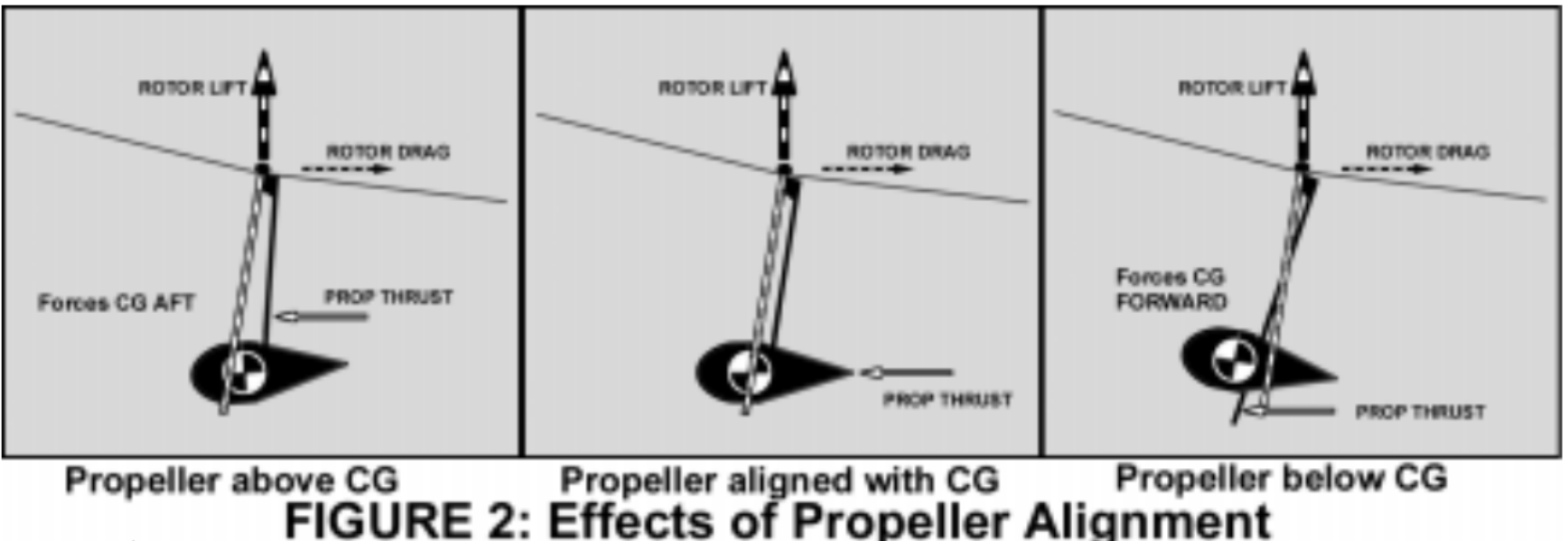
• A Propeller Thrustline vertically positioned IN_LINE with the CG will initially cause the CG to be positioned directly ON the RTV - at ALL power and speed settings.
• A propeller thrustline positioned above the CG, by itself with no restoring forces, will cause the CG to shift close to, and possibly behind the RLV - a less than ideal configuration.
• A Propeller Thrustline vertically positioned BELOW the CG will initially cause the CG to be positioned FORWARD of the RTV - A GOOD thing!
Center of Drag (CD):
Viewed from the front of the gyro, the CD is the vertical point at which the total rotor AND airframe drag can be said to be concentrated. The vertical positioning of this CD is important in consideration of the pitching moments created by its position relative to the CG. The vertical position of the CD may vary with airspeed and angle of incidence of the airframe to the relative wind. The total drag (in pounds) increases greatly with forward airspeed and is highly dependent on the aerodynamic shape (or lack thereof) of all components of the air- frame including wheels, landing gear, fuselage, mast and rotorhead. The airframe drag increases by the square of the airspeed, so the CD becomes a more relevant factor at higher speeds. For clarity of the effects of airframe drag on the position of the CG, this discussion will treat the AIRFRAME drag and ROTOR drag separately. Rotor drag may sometimes be referred to as INDUCED drag—the drag of the rotor created as a function of creating LIFT. Airframe drag may sometimes be referred to as PARASITIC drag—the drag of all other airframe components that are not related to the creation of lift. Airframe or parasitic drag increases dramatically at higher airspeeds with the square of airspeed. Rotor or induced drag is a function of the amount of lift created, and is minimum at the best Lift/Drag (L/D) of the rotor—typically in common gyros, about 45 mph. The propeller/engine thrust (in pounds), in steady flight, equals the total drag of the airframe AND rotor (at that throttle setting).

The Center of Drag (CD) is important in consideration of its pitching moment relative to the Propeller Thrustline (Figure 3). At higher airspeeds, this moment between a higher Propeller Thrustline and a lower CD tends to rotate the airframe and CG aft relative to the RTV, making the gyro more unstable or sensitive in control and to wind gusts.
Horizontal Stabilizer (HS):
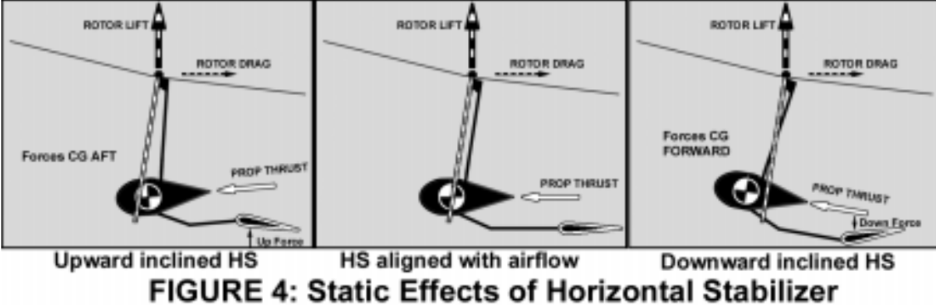
A horizontal stabilizer may serve to correct or compensate for other pitching moments, depending on size, placement and angle of incidence of the horizontal stabilizer (Figure 4). Without a Horizontal Stabilizer or any other alternative aerodynamic moments to force a pitch up on the airframe (CG forced forward), the Propeller Thrustline must be located in line with or below the CG or CD to create a static moment that holds the CG adequately forward.
Static Pitching Mechanisms:
The Dynamic Stability of a gyro is strongly a function of the longitudinal (fore/aft) STATIC position of the CG - relative to the RTV. (This dynamic stability effect will be discussed in the next installment of this series of articles.) Statically, there are three equally significant thrust and aerodynamic moments which determine the STATIC pitch attitude of the airframe and thereby determine the STATIC longitudinal position of the CG - relative to the RTV. It is important to understand that it is the combination of these three moments that determine the STATIC position the CG for adequate DYNAMIC stability. It is a gross mis-presentation of the stability issue to focus on only one or two of these factors.
To visualize these moments, these three mechanisms are depicted separately by considering that each of the other moments are nonexistent or cancelled for that depiction. Also, for this STATIC analysis, it is helpful to resolve the rotor thrust (RTV) into two component vectors - LIFT and DRAG of the rotor. (See Rotor THRUST, LIFT and DRAG sidebar) Later, in the DYNAMIC stability discussion in the next installment, it will be more convenient to treat the RTV in its single, non-resolved THRUST vector depiction.
1. Propeller Thrust position relative to the CG (Figure 5):

This is the gyro feature that receives so much attention and debate. Figure 5 depicts a “drag-free” airframe with no horizontal stabilizer. For un-accelerated level flight (steady state), without airframe drag and without a horizontal stabilizer, the propeller thrust exactly equals the rotor drag. Note that this is true for whatever power or level airspeed we choose. If the rotor drag is less because the airspeed is different, the propeller thrust will be less as well - for level flight. The offset between the rotor drag vector and the propeller thrust vector creates a moment that rotates the airframe (and CG) forward. Considering the opposite balancing moment between the rotor Lift and the CG weight, these two moments balance to hold the CG forward to a certain angle - typically to the normal flight angle of 9 degrees or so. If you do the Trigonometry, you discover that the vertical location of the propeller thrustline relative to the CG determines how far forward the CG can be pushed - relative to the RTV. In fact, it works out that if the Propeller and CG are exactly aligned, the CG is rotated forward the same exact angle that the rotor is tilted back - the Lift/Drag ratio of the rotor or typically 9 degrees. This is true regardless of power or airspeed in steady, level flight. This is depicted in the center figure in Figure 2.
The Trig also reveals that the CG is rotated forward by a different angle if the propeller thrustline and CG are not aligned, as depicted in the first and third figures in Figure 2. Keep in mind, this is ignoring the other two static moments on the airframe - CD and a horizontal stabilizer. So, a lower propeller thrustline (drop keel) can position the CG to the more desirable forward longitudinal STATIC position for improved DYNAMIC stability. Note that the gyro designer may elect to angle the engine and Propeller Thrustline up or down so as to reduce this static pitching moment in either direction.
2. CD relative to Propeller Thrustline (Refer to Figure 3, page 24):
This is the gyro feature that receives much less attention but may actually be the predominant factor in gyro instability at higher airspeed. When the airframe is forced “nose-low” under any condition, the CG has physically moved aft toward a less DYNAMICALLY stable position. Airframe CD is a less controllable factor. The total airframe CD is a sum of the drag factors of all the airframe components including wheels, fuselage, struts, etc. Making this worse, the drag of all these components increases with the square of the airspeed. Suffice it to say, it is hard to determine just where the CD is located and where it moves to, at different airspeeds and airframe deck angles!

Figure 3 depicts the same gyro as Figure 5 (page 25). But this time airframe drag is represented graphically to show the effect of the offset between the CD and the Propeller Thrustline. Figure 3 depicts the Propeller Thrustline aligned with the CG, so that that moment itself is not a factor or pitching moment. Intuitively (and with trigonometry) you can see that any offset between the CD and the Propeller Thrustline also causes the CG to rotate fore or aft of the RTV as depicted in the first and third figures in figure 3. Note that, as in (1) above, the gyro designer may elect to angle the engine and Propeller Thrustline up or down so as to reduce this static pitching moment in either direction. But, note also that it is much more difficult for the designer to determine or predict the location of the CD - especially for non-aerodynamically clean airframes.
3. Horizontal Stabilizer (Refer to Figure 4 page 25):
This is the major tool or feature the gyro designer can use to position the CG relative to the RTV. As seen in Figure 4, the CG can be positioned statically forward nearly as much as desired with the use of an adequately powerful inclined horizontal stabilizer. The designer may position the Horizontal Stabilizer in the free airstream to make its pitch effect a pure function of airspeed. Or, he may position it wholly or somewhat in the prop blast to make its effect a function of engine power AND airspeed - such as to compensate for an opposing propeller thrust or CD moment. The angle of incidence of the HS may be utilized to compensate, a lot or a little, for an otherwise “nose-low” (CG aft) airframe attitude. The combination of these three STATIC pitch moments or factors determine the longitudinal position of the CG relative to the RLV – at a specific flight condition. As these flight conditions change, the relevant forces and moments arms change, and the CG may end up in a different position relative to the RTV. Since this relative position is a major factor in flight stability (as will be explored in the next installment), this often can lead to significantly different handling and control qualities at different airspeeds, power settings and loading.
Re-stating the purpose of this series of articles: To raise understanding and awareness of the many complicated issues, which limit your personal safe gyro flight envelope. The major cause of gyro fatalities is pilot and machine susceptibilities to instabilities, which ultimately can result in a PPO event. Certainly, every person who has ever seriously contemplated gyro flight well understands the imperative to “never reverse the airflow through the rotor” - or said another way, “never cause negative g’s!” However, it is not enough to consciously avoid ever doing that (jabbing the stick forward, or pushing over the top of a zoom). From the numerous PPO fatalities we continue to experience, it is obvious there is more to it than simply “never doing it”! There may be conditions at the extremes of each of our personal safe gyro flight envelopes where we and/or the machine are not equipped to avoid the events leading up to the final PPO. The next installment of this series will discuss how these STATIC moments, establishing the STATIC position of the CG relative to the RTV, effect and in large measure, determine the DYNAMIC flight characteristics and stability of your gyro.
Credit and Thanks. I would like to acknowledge a special thanks to Mike Jackson for his assistance and encouragement in preparing this and the next several installments on gyro stability. Mike is a 21-year Air Force pilot (retired), has a degree in Aerospace Engineering from the University of Colorado, and is a graduate of the USAF Test Pilot School. Mike’s Air Force experience is mostly in fighter jets, but he has owned a Cub and a Tiger Moth, and has flown a “smattering” of helicpopters and “a gyro.” In assistance on this article, Mike has dusted off his old Test Pilot textbooks and has consorted with fellow test pilots who have experience in the helicopter area. Mike is currently flying heavy iron for Southwest Airlines and describes himself as a “gyro wannabe.” We are truly fortunate to at- tract such people as Mike to our sport, and to avail ourselves of such back- ground and skills. Thanks, Mike!