
The Stability Tools
Part 5
By Greg Gremminger
In this installment we will explore other factors that affect the stability of a gyro and some of the tools and techniques the gyro designer may employ to address these stability issues. We will also suggest some criteria that might be used to assess the stability of your particular gyro.
The Stability Tools:
Lest you get the impression from the previous installment, those gyros are untamed beasts requiring super-human skills to avoid a bad day, that is not necessarily the case. There are numerous pitch stability factors that might contribute to a bad day, but gyros are also extremely capable and forgiving flying machines and can be readily tamed, even in less-experienced hands, by careful design.
Previously we discussed the government requirements for fixed-wing certification that, even without many of the stability and control aggravating mechanisms that exist in gyros, fixed-wing aircraft be stable in BOTH the “stick free” AND the “stick fixed” modes! That is to say, the government does not depend on pilot skills to correct unstable situations in certified aircraft! They probably do this for a reason - they may have learned that Murphy often rules the airways also - “if it can happen it will!” Gyros CAN be configured to meet these same stability criteria in all flight regimes in the hands of most pilots and under both stick free and stick fixed modes. To achieve this, designers have many tools available, including:
Vertical position and angle of the Propeller Thrustline
Vertical position of the Center of Drag (CD)
Vertical position of the Center of Gravity (CG)
Use of a Horizontal Stabilizer (HS)
Aerodynamics and streamlining of the airframe
Moment of Inertia of the rotor
Moment of inertia of the airframe
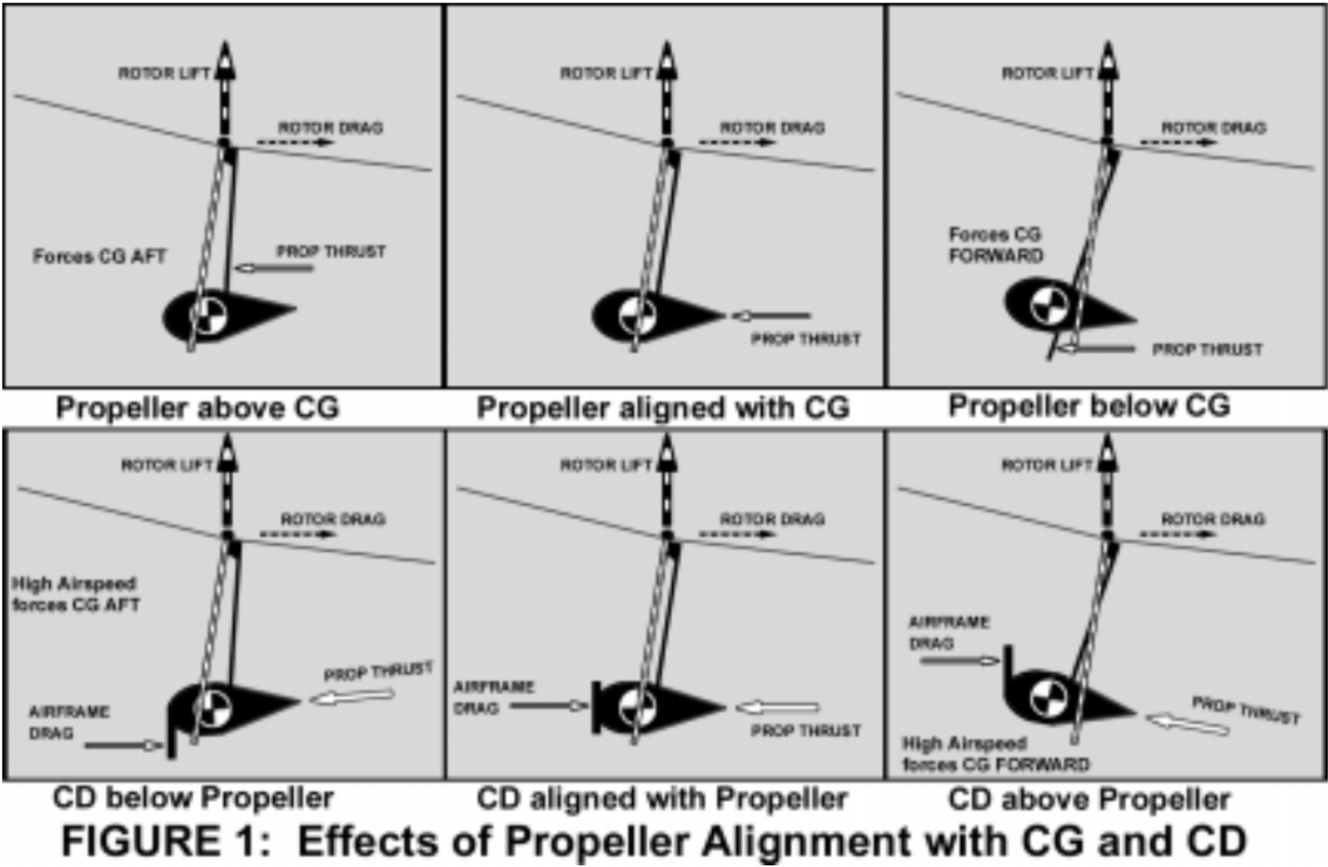
1, 2 and 3: As shown in Figure 1, the vertical position of the Propeller Thrustline relative to the airframe CG and/or the CD can position the CG fore or aft relative to the RTV. The lower the Prop Thrustline, the further forward the CG will be located in flight. The higher the CD, the further forward the CG will be located in flight.
Airspeed may change the pitching moment from the CD, depending on the CD location relative to the CG or Propeller Thrustline, due to changes in the location of the airframe CD and/or the total drag on the airframe.
Some designers may not find it desirable from an aesthetics or configuration standpoint to lower the Propeller Thrustline as far as required to achieve a dynamically stable CG location from propeller thrustline alone. In this case, the designer may utilize a Horizontal Stabilizer to compensate or balance the adverse static moments from the offset propeller thrustline.
4: A Horizontal Stabilizer (HS) can provide a double benefit for the price of one! The HS can readily apply a STATIC airframe nose-up moment to position the CG well forward of the RTV – as discussed in a previous installment of this series of articles.
This, in itself can improve the DYNAMIC stability of the machine if the designer so configures the HS to raise the nose or to hold it up as a function of airspeed and/or engine power/thrust.
A HS has another major beneficial impact - aside from helping to position and hold the CG statically forward, the HS will also aerodynamically hinder any DYNAMIC pitching of the airframe - much as do the feathers on an arrow. A vertical gust will raise or lower the air- frame nose into the vertical gust - exactly as it does on a fixed-wing aircraft. This effect is the more intuitively appreciated effect and considerably adds to the DYNAMIC stability margin.
The combination of the STATIC pitching effect and of the DYNAMIC stabilizing effect can give the HS a double whammy benefit for the price of one set of feathers! In my opinion, the bigger the HS the better - not just the Cierva guideline of 12-15%. The Cierva guideline was determined empirically on the almost purely centerline thrust and drag tractor Autogyros of the 1930’s.
This 12-15% factor was determined to be adequate for stabilizing the naturally unstable rotor system alone - there was little need to stabilize the airframe in the Cierva configuration. Today’s pusher gyros need to stabilize the rotor system as well as the airframe.
5: Aerodynamic shape and efficiency of the fuselage and other airframe components can be effectively used to raise the vertical location of the CD and to alter any nose-down tendencies induced aerodynamically over the airframe. Often, however, the use of a significant fuselage, because it is forward of the CG, can be destabilizing itself, requiring extra Horizontal and Vertical stabilizer volume to negate the effects.
6: The spinning rotor itself can help slow down or counter some destabilizing characteristics of the gyro configuration. The rotor has a very high Moment of Inertia (MOI) - gyroscopic action that resists the pitching of the disk. The MOI may be increased with use of a heavier or faster spinning rotor. In the absence of cyclic control inputs, the rotor tends to ignore all these pitching mechanisms and movements of the airframe - this is GOOD. That is why the gyro/pilot system tends to ignore destabilizing pitching movements, IF the pilot is not restricting stick movement or commanding other destabilizing rotor reactions (Pilot Induced Oscillations -PIO)! Heavier or faster rotors, however, strongly determine other handling characteristics the designer may also be concerned, such as stick forces - it is all a trade-off!
7: Airframe Moment of Inertia (MOI): Now here is an interesting parameter available to the designer. The MOI of any object is determined by its weight AND by how tightly all its weight is concentrated around its CG. In other words a 2-seat tandem gyro will have a higher airframe MOI than a 2-seat side-by-side model because one pilot is further forward and the engine is further aft of the CG to balance that forward seat. The tighter mass concentration, such as in a side-by-side configuration is often referred too as “close coupled”. This means that the lower airframe MOI or “close coupled” machine will accelerate more quickly in pitch rotation with the same moments applied, than the higher MOI gyro will. For instance, if both a tandem and a side-by-side gyro weigh the same, the tandem will be more stable in turbulence- simply because any moments resulting from turbulence (lift and drag changes) will have a slower effect on pitching the airframe. This applies for single seat gyros as well, and can help explain why perhaps a lot of PIO and PPO accidents occur in the very light machines.
All of these above tools (and others) can be applied alone or in combinations to improve stability. No single factor or tool is likely to determine the stability of the overall gyro/pilot system. There are many trade-offs; and all design goals may not be fully achievable. These tools and factors may change dramatically in their effect at higher power, higher speeds, lighter or heavier loads, etc. Indeed, some of these factors may contribute to instabilities under unfamiliar or extreme conditions. Since full scale wind tunnels are not generally available to the average gyro designer, and since gyros are almost as complicated to model in computers as helicopters are, only trial and error and iterative testing by the designer can approach the desired results. And then, each designer may have different desired results.
Gyros are designed for many purposes and many design goals. Some may be designed to be lightweight or inexpenive. Others may be designed for extreme maneuverability, or for high speed utility. Even a machine that meets all of it’s designer’s goals may be unsuitable for flight outside the envelope the designer intended or outside the capabilities of the pilot. Even a machine that demonstrates good static stability (flies steady and easily in smooth air) may surprisingly demonstrate dynamic instabilities in other conditions or in the hands of an unfamiliar pilot.