
Magni Rotor
Part 1
By Greg Gremminger
Precision Composite Rotor Blades:
The Magni rotor and rotor system is very unique. It is fabricated under precise procedures and autoclave processes from high‐tech composite materials – carbon fiber and fiberglass. The precision of this process controls very exacting geometric and mass distribution consistency for superior balance. The “balance” of any rotor system requires the aerodynamic axis of lift to be coincident with the mass axis and the exact spinning axis of the rotor. Most rotor systems using extruded and/or fabricated components have difficulty in exactly matching these two centers exactly, with rotor balance being a compromise between the two. The precise control of the fabrication of each Magni rotor blade, where each station of the rotor from root to tip is an exact reflection of that station on the opposite rotor, precisely aligns all three axes for unsurpassed rotor smoothness. Unlike other composite gyroplane rotor blades, Magni does not mix an aluminum spar with composite materials – the process of curing the composite materials in an autoclave causes geometric distortions and a minimum, due to the mismatched coefficients of expansion of the two materials under heat. By using a carbon fiber spar the full length of the rotor blade, the autoclave process yields precise geometry and mass distribution on each rotor blade. Magni gyros have been renowned for the smoothness of their rotor system.
High Inertia Rotor:
Magni’s composite rotor blades are indeed heavy – about twice as heavy as most other blades of similar size. Some would tout this as a disadvantage to high maneuverability, but the high inertia of a heavy rotor provides very forgiving flight and significant control and stability advantages. Traditional gyrocopters had very light stick forces – could hardly feel when you were moving the stick. Many in the gyro community consider this light stick characteristic to be a sporty advantage and why gyros are so highly maneuverable. What is not so popularly admitted is that this lack of sensation of stick pressure and stick movement has actually contributed to the traditional buntover and/or Pilot Induced Oscillations that are so famously attributed to traditional gyros! Because of the sensitive nature of cyclic rotorcraft control, very slight unfelt movements of the stick can result in rapid and surprising maneuvering – often inadvertent and unintentional from startled novice pilot reactions. Pilots of all aircraft fly by the feel of stick or yoke pressure in their hand and arm, not by the less precisely sensed actual movement of their hand or arm. When stick feedback pressures cannot be readily felt by the pilot’s hand or arm, the tendency for over‐ control is possible because, without this stick feel, the pilot needs to wait for a reaction in the attitude of the airframe or a corresponding feel of G‐Load in their “seat of the pants”. In fact, proficient pilots subconsciously learn to gage their proper and precise control input with the consistency of the feel of the stick and the corresponding seat of the pants G‐Load sensations in their seat, back, shoulders and neck. It is this consistency between the feel of the stick and the feel of their “seat” that makes proficient pilots able to fly with precision, and/or to recognize a mismatch in these two sensations. A subconsciously detected mismatch would indicate entering into an uncomfortable realm of instability where stick pressures are not timed with or proportional to the pilot’s “seat of the pants” G‐meter. For this reason, Magni gyros intentionally provide strong stick “feedback” feel to help especially new pilots avoid any tendencies to over control and possibly initiate Pilot Induced Oscillations. When a pilot has little feel of the resistant pressure in the cyclic stick, as seems to be desired by many for “light touch” maneuverability, there is also the tendency for less proficient pilots to over control. Lately, there seems to be recognition among more in the gyro community that higher inertia blades actually provide this safety advantage. The option of tip weights in some of the lighter aluminum rotor blades is becoming more popular. Most describe this as “more forgiving”. As far as a maneuverability disadvantage of a heavier rotor and stronger stick forces, the rotor still responds to commanded cyclic displacement inputs and will still maneuver just as much and quickly as any similar weight gyro – just need to use a little muscle to make more severe maneuvers while the heavier stick reminds you that you are making them.
Magni’s higher inertia rotor presents another stability advantage. As discussed above, DYNAMIC pitch damping is an advantage to stability, avoiding buntover and Pilot Induced Oscillations, turbulence reaction, etc. Above we were talking about AIRFRAME dynamic pitch damping. But the spinning ROTOR also has its own independent DYNAMIC pitch (and roll) damping properties. These properties are a function of the rotor RPM, and of the inertia of the rotor. Now, the airframe and the rotor are independent inertial DYNAMIC systems. But, they are both interacting with each other – the rotor interacts with the airframe pitch through the Rotor Lift Vector lifting or lowering the nose, and the airframe interacts with the rotor through cyclic inputs of the rotor spindle which tilts with the airframe whenever the airframe pitches or rolls. Any two dynamic inertial systems that can mutually affect each other can either excite or dampen harmonic reactions in the whole system. When the two natural response rates or natural oscillation frequencies interact they can create desirable or undesirable harmonies as a total system. Picture a child swinging their legs on a long swing. When his legs are swinging in phase and synchrony with the swings of the swing, the swing oscillations grow. When their legs are swinging in the opposing phase with the swing, the oscillations dampen – can be slowed down to a stop. When the child swings their legs out of synchrony with the natural swinging oscillations of the swing, very erratic movements of the swinging swing are generated. Now picture this whole swing system with a child on a very short swing. More difficult to harmonize leg swings with swing swings! This is analogous to a rotor system that either matches or harmonizes with the natural rates and frequency of the airframe, or not. The heavier Magni rotor is designed to match or harmonize with the airframe dynamic reactions to produce a total harmonized response to pilot input and/or turbulence disturbances. A heavier rotor already has an inherent advantage in damping turbulence disturbances simply because of its higher inertia. But, a rotor system that is dynamically harmonized properly with the airframe, as the heavier Magni rotor is, makes the whole aircraft control and responses much more desirable and intuitive. This is often recognized by pilots who fly various brands and models of gyros – the Magni is more comfortable flying in heavy turbulence. The higher inertia rotor matched dynamically with the airframe is the reason. In short, there are other issues to consider when choosing a rotor to install on a gyroplane, or any rotorcraft, other than it is simply light or cheap. Magni has done the development work to evolve this desirable harmony between the two systems.
Rotorhead configuration:
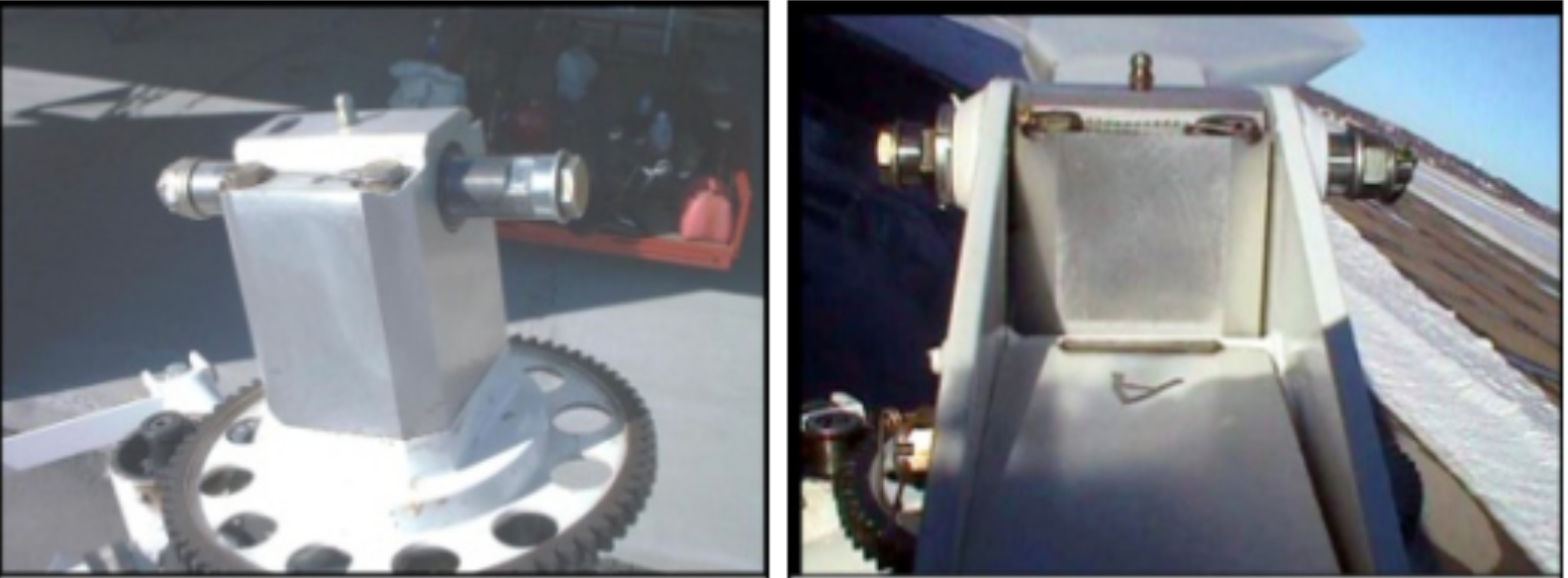
The Magni rotor system as a whole is very unique in the gyro world. Examine the pictures below. There are no similar rotorhead configurations to the Magni configuration. Most rotorhead configurations are variations on the Bensen rotorhead. The Magni rotorhead does not use the rather thin “teeter towers” that can flex sideways with loads on the rotor. Magni uses a solid “teeter block” that includes the internal large main double ball bearings. The block cannot flex in any direction. Flexure of “teeter towers”, especially on heavier 2‐place gyros where taller “towers” are necessary, creates 2‐per‐rev rotor shake.
The Magni hubbar uses two thick welded steel plates that straddle the teeter block. The rotor blades bolt sandwiched between the two hubbar side plates with large horizontal bolts. There are no provisions for adjusting either the blade pitch or the “string” alignment of the two rotors. The blade pitch and “string” are controlled by the very precise fabrication of the rotor blades that provide for very exacting blade aerodynamic and weight symmetry between the two blades. The traditional rotor head and hubbar configuration requires adjustments of both blade pitch and blade “string”. (“Stringing” gets its name from the process of stretching a string from one blade tip to the other to adjust the alignment of the blade attachment to the hubbar so that the stretched string centers over the top of the hub bar. The idea is to tighten the attachment bolts with the two blades aligned geometrically exactly 180 degrees across from each other.) These adjustments are necessary in less precisely fabricated rotors in order to find the best compromise between the rotor center of mass and its aerodynamic center – and its spindle spinning axis. The common rotor head and hubbar configurations attach the blades to the hubbar with a series of smaller vertical bolts that allow some lateral adjustment in the bolt hole tolerances to make the “string” adjustment. Traditional rotor configurations allow for a method also to adjust or shim the pitch of the blades relative to each other – to compensate for aerodynamic imbalances between the two blades. (The disappointing thing about this whole process is that the stretched “string” may identify the geometric center to the two blades. But, with less precise blade construction or fabrication, this does not assure that either the mass center or the aerodynamic center will be aligned with the spinning axis of the spindle. Such adjustments on most rotors are a compromise of all these centers – some rotors can be made smoother, and some just cannot because of varying imprecision of the rotor blade mass distribution and blade/airfoil geometry.)
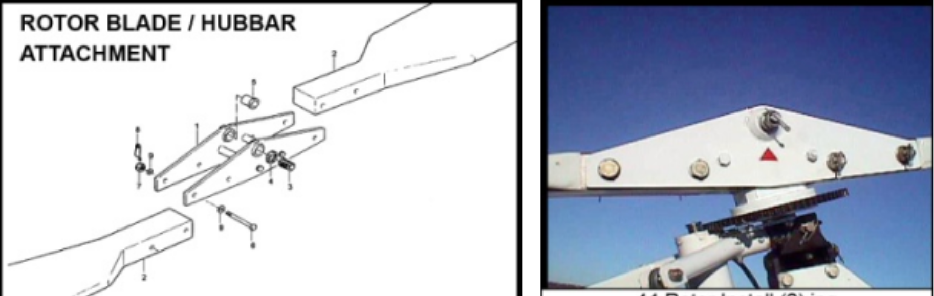
Magni composite rotor blades are fabricated with such precision that these “string” and blade pitch adjustments are not necessary. Each blade is then precisely matched to its partner based on very precise measurements. The absence of such adjustments assures the alignment cannot change while also assuring consistent re‐assembly without time‐ consuming “stringing” of the blades. The two horizontal bolt attachments of the blades to the hubbar assure consistent “string” and blade pitch repeatability.
Rotorhead teeter bearings:
Few gyroplane rotor systems, in the interest of lower costs, use actual bearings for teeter bearings. Some may use roller or pin radial bearings for the teetering action, but others simply use brass and steel sleeve bearings. To minimize teeter 2‐per‐rev rotor shake, friction in the teeter action must be as low as possible. Sleeve bearings can get dirty or even gall over time – adding friction that shows up in rotor shake. Another consideration in the teeter bearing is to minimize any ability of the rotor hubbar to slide sideways on the teeter bolt. Most gyro rotor systems specify plastic shims that may allow as much as .010 inch side play of the rotor – this is what Igor Bensen allowed in his original Gyrocopter. Any side to side play on the teeter bolt adds another strong significant source of 2‐per‐rev rotor shake.
Magni rotor heads use compound bearings for teeter bearings – mounted in the solid “teeter block”. These compound bearings have both radial and axial roller bearing surfaces. With both radial and axial bearings, the Magni teeter bolt arrangement allows ALL axial play to be removed – to eliminate that source of 2‐per‐ rev rotor shake. The Magni teeter bolt configuration also provides side‐to‐side (chord wise) adjustment of the rotor on the teeter block – to easily fine tune any remaining chord imbalance of the rotor. (Some other quality rotors do also provide for precise chord wise adjustments, but most simply require adjusting shim thicknesses to fine tune chord balance.) For many rotors, these adjustments are very necessary, and time consuming to do, in order to find a less than perfect compromise for the inherent rotor blade mass, geometric and aerodynamic imprecision.
Rotor life:
The fatigue life of rotors is a common consideration for all rotorcraft. While some of the simpler single‐seat gyros do not actually rack up long operational lifetimes, many of the current crop of new generation gyroplanes require significant investment and should be expected, with reasonable care and regular maintenance, to last for many years and hours of enjoyment. Unfortunately, there are questionable lifetimes for several popular rotor systems on the market today. The questions have arisen when operators in recent years have found fatigue cracks in aluminum hubbars and blade attachment areas on relatively low operational hour gyros. Some producers have necessarily required close frequent inspections and relatively low‐time mandatory replacement of rotor blades and other rotor components. Just the known history of such issues, to me, makes flying with those components a bit stressful.
The Magni composite rotors avoid the traditional fatigue life issues of many rotors. There are Magni rotor blade assemblies that have flown in excess of 3000 hours – most of those in rugged training hours with students. There have never been any reported rotor failures or even structural cracks with Magni rotors – other than obvious rotor strikes with hard objects. (Most Magni composite rotor damage, deep gouges and other impact damage, are easily repaired.) Barring an actual crash, most damage is usually cosmetic only. Magni does now however, require replacement of rotor blades at 2500 operational hours. This is mostly so that the factory can evaluate such high time rotors to see if there are any issues developing, and to eventually determine if the 2500 lifetime limit can be extended. 2500 hours is exceptional for rotor life on any rotorcraft, and certainly much better than some rotors which are life limited at even less than 1000 hours!
Full composite material construction is a major reason for the long trouble free life of Magni rotor blades. But the Magni hubbar attachment with large lateral bolts, rather than vertical bolting, avoids top side and bottom side stressor points at the bolt holes and hubbar tips that would focus the fatigue stress at those most critically stressed root attachments points. With the high stress concentration points unavoidable with common vertical attachment bolts and holes, extruded spars and even full extrusions may be prone to stress fatigue cracks at or near these stressor points – often difficult to observe internally. Magni simply avoids all of these issues with use of a full carbon fiber spar and fiberglass construction. The Magni rotor spar consists of a large number of unidirectional carbon fiber strips, routed tip to root through a rounded window in a massive aluminum attachment hub block at the root of each blade. The horizontal configuration attachment bolts – two very large bolts that sandwich the aluminum attachment hub between the hubbar steel plates – avoid the stressor points created by vertical bolts holes and the tip of the hubbar on standard configuration rotors. As far as we know, Magni is the only producer that uses this entire rotor and hubbar configuration. As far as we know, there have been no normal use failures of Magni rotors or hubbars in the 20‐30 years that this design has been in operation. Even a popular fiberglass rotor blade that employed an aluminum spar and standard vertical blade attachment bolts had severely limited life and experienced numerous cracking issues. If there is one issue that really takes the fun out of flying, it is probably having doubts about the structure and reliability of the rotor!